Precautions when using and installing the LED driver
2022-02-17(1119)views
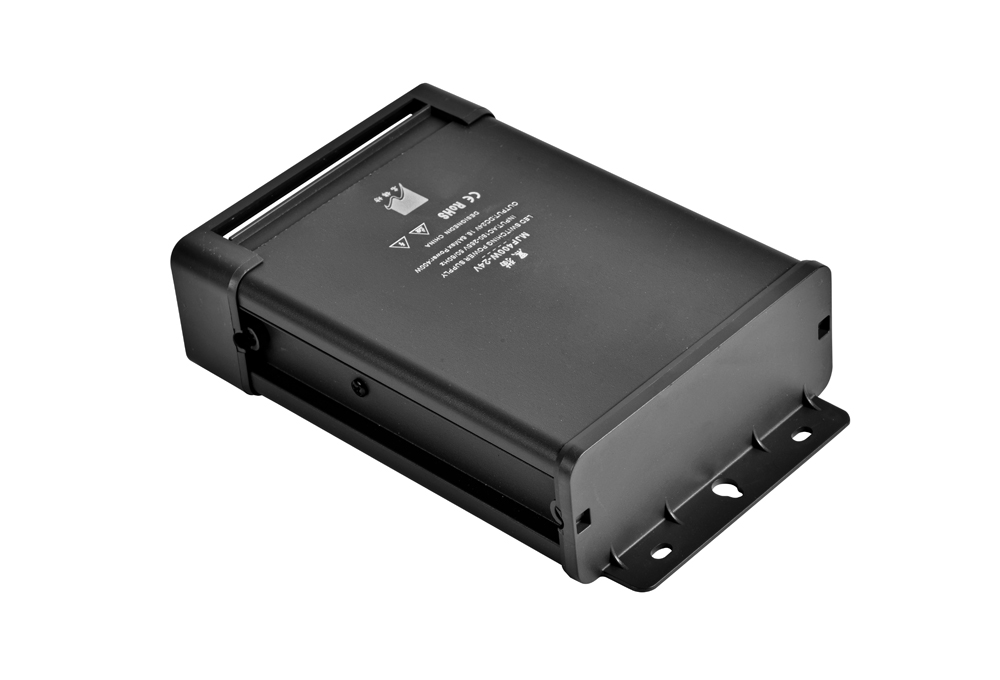
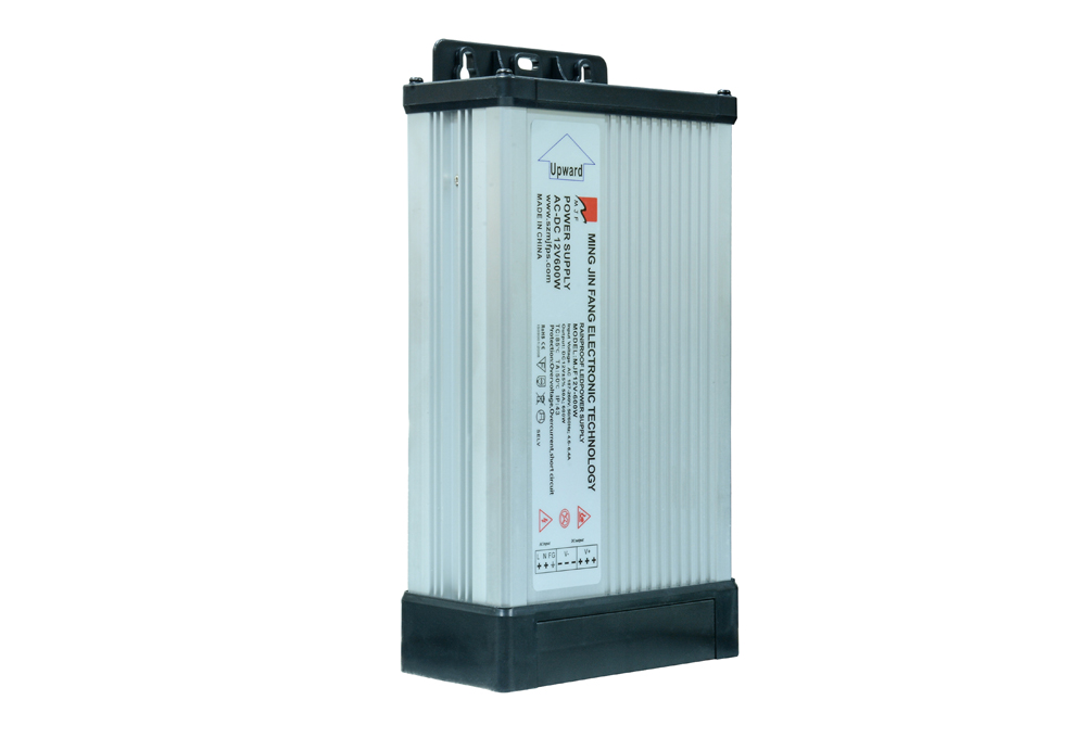
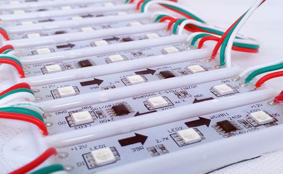
Correct use and installation of LED driver power supply will help prolong the service life of LED lamps and power supplies.
1. Use LED derating.
2. Use linear constant current driver, pay special attention to its working pressure difference.
3. The secondary output power supply of the isolated switch constant current driver should not be suspended, and the negative electrode should be grounded.
4. For the switching constant current driver, the operation sequence of connecting the LED light first and then turning on the power supply of the driver must be strictly followed. If you do the opposite, at the moment when the LED light is turned on, there will be a huge inrush current flowing through the LED light, threatening the safety of the LED light.
The solution to the instantaneous current impact problem is to add a current limiting circuit at the output end. There are two main implementations.
a, series connection
The excess energy is dissipated inside the current limiting circuit. By blocking the excess energy before the load, it is ensured that the current flowing through the LED lamp load at the moment when the connection switch is closed is within the allowable current range of the LED lamp.
Series current limiting circuit: It is configured between the high frequency filter capacitor and the constant current loop, and includes a collector-emitter channel of an NPN transistor on a lateral branch and a current limiting resistor connected in series with the collector-emitter channel. The collector junction bias resistor is connected between the collector and the base of the NPN transistor. The base of the NPN transistor is connected to the emitter of the NPN transistor, the collector of the NPN transistor is connected to the base of the NPN transistor, and the emitter of the NPN transistor is connected to one end of the current limiting resistor. At the same time, the current limiting circuit can be connected in series between the constant current resistor and the voltage limiting circuit, between the voltage limiting circuit and the connection switch, or between the load and the output pole potential.
When the output current is lower than the preset current limiting value, the voltage drop on the current limiting resistor is lower than 0.7V, the NPN transistor is in an off state, and the NPN transistor is in a saturated conduction state. The circuit works fine with only a small amount of loss added to the current limiting resistor and the NPN transistor. When the output current is greater than the preset current limit value, a voltage drop higher than 0.7V will be generated on the current limiting resistor. At this time, the NPN transistor is saturated and turned on, and the emitter-collector channel of the NPN transistor, etc. The effective resistance value increases, which limits the output current and effectively protects the short-term overcurrent phenomenon on the load.
b. Parallel connection
Also, the excess energy is dissipated inside the current limiting circuit. By leading the excess energy to the current limiting circuit, it is ensured that the current flowing through the LED lamp is within the safe current range of the LED lamp.
Parallel current limiting circuit: It is configured between the output voltage limiting circuit and the load, and a collector-emitter channel of an NPN transistor is connected in parallel on a vertical branch. The base of the NPN transistor is connected to the negative potential of the load to limit the current. A resistor is connected between the emitter and base of the NPN transistor. The collector-emitter channel of the NPN transistor can be on any vertical branch after the capacitor.
When the output current value is less than the preset threshold current, the voltage drop across the current limiting resistor is less than 0.7V, the NPN transistor is in the off state, and the circuit works normally; when the output current value is greater than the preset threshold current, the current limiting The voltage drop across the resistor is greater than 0.7V, and the collector-emitter channel of the NPN transistor becomes a low resistance value, so that most of the current flows through the collector-emitter channel of the NPN transistor and is consumed in the form of heat energy. On the collector junction of the NPN transistor, the transient overcurrent phenomenon on the load is effectively protected.
Latest News
-

What factors should be considered when choosing a switching power supply?
A large production enterprise needs a lot of intelligent eq...
-

What are the conversion methods of switching power supply?
The so-called switching power supply, as the name implies, ...
-

company profile
Shenzhen Mingjinfang Electronic Technology Co., Ltd. was est...
-

The selection of LED switching power supply should consider many factors
1. Select the appropriate input voltage range: Take AC input...
0755-27221809
Service Hotline:0755-27221809
Telephone:181 2882 0589
Fax:0755-27479339
Email:[email protected]
Address:3rd Floor, Building A, Shengfeng Industrial Park, Helishan Road, North Yanchuan, Songgang, Baoan District, Shenzhen


 0755-27221809